
Plastic Crate Mold Design: Key Points for Injection Molding
1. Wall Thickness
Uniform wall thickness is the most critical principle in crate design. It directly affects structural strength, sink marks, cycle time, and material cost.
Recommended Range
3 – 5 mm for standard crates.
- Below 3 mm → risks rigidity and impact resistance
- Above 6 mm → increases cost, cycle time, and creates sink marks
Key Rules
- Keep thickness consistent across the crate
- Any section > 1.5× nominal wall creates visible sink marks on the opposite surface
- Use radius fillets at wall junctions to reduce stress concentration
2. Draft Angle
Draft angle — the taper applied to vertical walls — is essential for smooth ejection and mold longevity.
| Surface Type | Minimum Draft Angle |
|---|---|
| Smooth / polished surface | 0.5° – 1° |
| Textured / anti-slip surface | 1° – 2° |
| Deep walls (> 100 mm) | 1.5° – 3° |
Insufficient draft causes surface scratches, part deformation, and accelerates mold wear. Both outer and inner walls require draft — this is a common oversight in part drawings.
3. Rib Design
Ribs add structural strength without increasing wall thickness. Follow these proportions to avoid sink marks and warpage.
Design Proportions
- Thickness: 50 – 70% of nominal wall
- Height: Maximum 3× wall thickness
- Spacing: Minimum 2× wall thickness between ribs
- Junction radius: 25 – 40% of rib thickness
Placement Tips
- Place ribs on the inner surface to avoid aesthetic defects
- Avoid ribs directly opposite each other on inner and outer walls — this causes warpage from uneven shrinkage
- Never make ribs equal or thicker than the main wall — guaranteed sink marks
4. Lip & Rim Design
The lip provides structural reinforcement, dust sealing, and a grip surface for manual and automated handling.
Dimensions
- Lip thickness: 1.2 – 1.5× nominal wall
- Lip height: 8 – 15 mm (standard crates)
Functional Features
- Chamfer outer edge (1 – 2 mm) to prevent stress cracking and improve ergonomics
- Add anti-slip grooves on the lip surface for cold chain and wet environments
- For robotic handling, specify flat anti-slip pads compatible with clamping grippers
5. Stacking System
The stacking interface determines a crate's efficiency in warehouse and logistics operations.
| Stacking Type | Application |
|---|---|
| Direct stack | Light-duty; crates stack lip-to-lip |
| Interlocking stack | Heavy-duty; upper feet lock into lower recess, prevents lateral shift |
Interlocking System Design Rules
- Foot depth should be 1.5 – 2 mm less than the recess depth to allow manufacturing tolerance
- Vertical clearance of minimum 2 mm at the four corner columns prevents binding
- For multi-size crate series, standardize stack interfaces at the earliest design stage
6. Material Selection
Material choice directly affects mechanical performance, environmental resistance, and total cost.
HDPE (High-Density Polyethylene)
- Best all-round choice for standard logistics crates
- Excellent impact resistance, cold chain to −40°C (with modifier)
- Good chemical resistance to acids, alkalis, and detergents
PP (Polypropylene)
- Higher stiffness and heat resistance — better for hot environments or near machinery
- More susceptible to impact damage below 0°C without modifier
Common Additives
- Impact modifier — essential for cold chain HDPE; adds 5 – 10% cost but significantly improves low-temperature toughness
- UV stabilizer — required for outdoor storage crates (typically 0.2 – 0.5% HALS additive)
- Recycled material — up to 30% blend acceptable for non-critical, cost-sensitive applications
7. Load Bearing Analysis
Understanding load requirements prevents both over-engineering (wasted material) and under-engineering (product failure).
Static Load vs. Dynamic Load
- Static load: weight when stationary (typically 200 – 500 kg for standard crates)
- Dynamic load: during handling, forklift, or conveyor transport — typically 1.5 – 2× static load due to vibration and shock
Rackable Crate Requirements
- Load concentrates on the four corner columns — not distributed across the full bottom
- All four corners must contact the rack beam simultaneously
Safety Factor Standard
- Design to a minimum safety factor of 3:1
- Example: a crate rated for 300 kg dynamic load should not fail until 900 kg
- Common testing standards: EN 13170 or ISTA 2A — deflection typically limited to ≤ 5 mm at full rated load
Ready to Start Your Crate Mold Project?
RISEMOULD offers free DFM analysis on all new crate mold projects. Send your part drawings today — we respond within 48 hours.

|

|

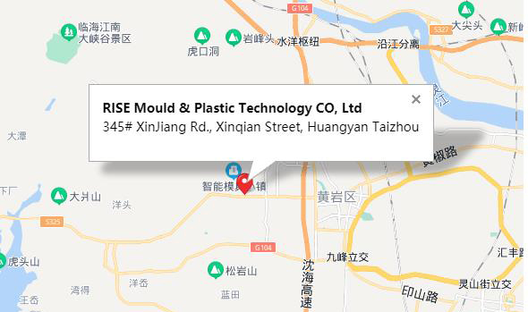
Rise Mould & Plastic Technology CO, Ltd 
345# XinJiang Rd., Xinqian Street, Huangyan Taizhou
export@risemould.com office@risemould.com |
|